Current Results
- Label free analyte detection using photonic crystal engineered waveguides
- a) Real-time monitoring of biotinylated bovine serum albumin/streptavidin reaction
- b) Real-time monitoring of hybridization reactions
- Label free detection using waveguide engineered with noble metal nanoparticles
- Detection of BRCA1 gene in real-time using fluorescently labeled PCR products:
- a) Selection of appropriate labels
- b) Real-time monitoring of hybridization and dehybridization reactions
- c) Discrimination between full-matching and mismatching sequences – Kinetic versus end-point measurements
- d) Sensor regeneration
- NEMOSLAB instrument evaluation using fluorescently labelled PCR products
- Single Binding Event Detection
Label free analyte detection using photonic crystal engineered waveguides
a) Real-time monitoring of biotinylated bovine serum albumin/streptavidin reaction
A latent photonic crystal was created on top of an 8-micron wide waveguide, biotitinylated bovine albumin was immobilized onto the surface and after blocking it was reacted with streptavidin.
As it is shown in figure 1, when the biotinylated BSA was adsorbed onto the surface (arrow 1-2), the latent photonic crystal was developed and a drop of the detector photocurrent was observed due to filtering of the waveguided light from the biomolecular grating. The addition of blocking protein (arrow 2-3) first resulted in a moderate signal drop and then the signal increased to its value before adsorption of biotinylated BSA. The signal drop observed at the beginning of the blocking step was attributed to coverage of protein free adsorbing sites onto the APTES lines, whereas the increase in the signal was due to coverage of the surface between the APTES lines. The complete coverage of the surface with biomolecules eliminated the latent pattern leading to the recurrence of the signal to its initial value. The reaction, however, of the immobilized biotinylated BSA with the streptavidin, revealed again the pattern and as a result a sharp signal drop was observed (arrow 3 to the end of graph).
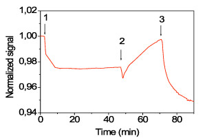
Figure 1. Real time monitoring of reactions performed onto waveguides engineered with photonic crystals. The sequence is as follows: up to arrow 1: washing with coating buffer; arrows 1-2: coating with 40 nM biotinylated BSA solution; arrows 2-3: blocking solution; arrow 3 to end: 10 nM streptavidin buffer in blocking solution. The signal was normalized in respect to its initial value.
b) Real-time monitoring of hybridization reactions
The immobilization onto waveguides of olígonucleotide probes as well as of their hybridization with the complementary sequences was monitored in real time using waveguides engineered with photonic crystals. Therefore, engineered waveguides coated with biotinylated BSA and blocked were reacted with a solution of pre-formed conjugate of streptavidin with a biotinylated probe corresponding to the wild type sequence of 3099delT mutation of BRCA1 gene (figure 2a). Then, after washing with the hybridization buffer, a solution of unlabeled complementary oligo was flow over the chip surface and the signal recording is depicted in frigure 2b. In both cases, there is a sharp drop in signal upon introduction of the oligo solution (arrow) making possible the label free monitoring of hybridization.
|
|
Figure 2. Real time monitoring of signal on waveguides engineered by photonic crystal upon immobilization of pre-formed streptavidin-biotinylated oligo conjugate (A) and hybridization with the unlabeled complementary oligo (B). Both reagents were used at a concentration of 500 nM, the flow rate was 20 μl/min and the signals were normalized in respect to their initial values.
Label free detection using waveguide engineered with noble metal nanoparticles
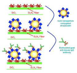
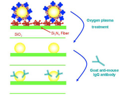
Two different approaches have been developed by IMEL/NCSRD and IRRP/NCSRD to immobilize gold nanoparticles onto the waveguides surface. In both approaches, gold nanoparticles with a mean diameter of 8.5 nm coated with streptavidin were immobilized onto the surface through binding to adsorbed biotinylated BSA as it is shown schematically in figure 3.
In the first approach, the adsorbed onto the particles streptavidin was used as a binder for the label free monitoring of a biotinylated goat anti-mouse IgG antibody reaction (Figure 3a).
According to the second approach, after immobilization of gold nanoparticles, the chip surface was oxidized in oxygen plasma so as to obtain plain gold nanoparticles onto the waveguide surface (Figure 3b). These nanoparticles can adsorb proteins in their surface and used for monitoring of biomolecular reactions as exemplified by monitoring in real-time the adsortion of an anti-mouse IgG antibody, the binding of mouse IgG and the immunoreaction with an anti-mouse IgG.
|
|
Figure 3. Schematic presentation of approaches used for immobilization of distinct of gold nanoparticles on top of the waveguide for label free detection of biomolecular reactions.
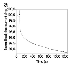
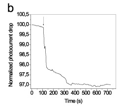
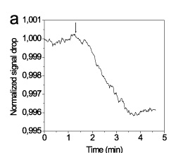
Both approaches provided measurable signal changes and proved in principle to be valid for label free monitoring of the biomolecular reactions (Figure 4).
 |
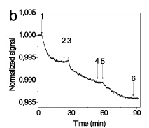 |
Figure 4. Real time signal monitoring from (A) a waveguide modified with streptavidin-gold nanoparticles conjugate by pumping a 1 nM biotinylated anti-mouse IgG antibody solution (arrow); (B) a waveguide modified with bare gold nanoparticles during immobilization of anti-mouse IgG antibody (150 nM) onto the surface (arrow 1-2), washing (arrow 2-3), immunoreaction with mouse IgG (10 nM; arrow 3-4), washing (arrow 4-5), and binding of anti-mouse IgG antibody (10 nM) onto mouse IgG (arrow 5-6).
Detection of BRCA1 gene in real-time using fluorescently labeled PCR products
a) Selection of appropriate labels
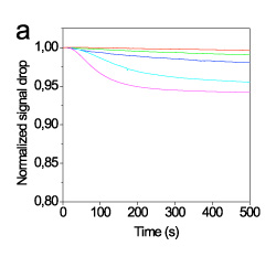
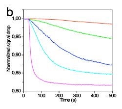
The efficiency of different fluorescent labels to induce a measurable photocurrent drop was evaluated using an oligonucleotide sequence which corresponded to wild sequence of 3099delT mutation in BRCA1 gene labeled with four different fluorescent labels: AlexaFluor 546 and AlexaFluor 647. Between the AlexaFluor labels the one with absorption maximum at 647 nm provided 3-times higher drop in detector photocurrent than that with absorption maximum at 546 nm (figure 5). This finding was expected to some extent since the absorption maximum of the first label matched to the emission maximum of LED.
|
|
Figure 5. Real-time signal obtained during hybridisation with a 2.5 (red line), 10 (green line), 40 (blue line), 160 (cyan line), and 500 nM (magenta line) solution in 1xHEN buffer of the full-matching sequence labelled with AlexaFluor 546 (A) or AlexaFluor 647 (B). The flow rate was 20 μl/min. The signals were normalized with respect to their initial value.
b) Real-time monitoring of hybridization and dehybridization reactions
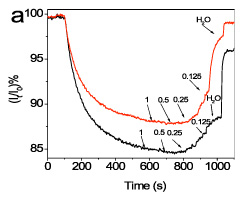
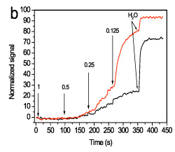
To achieve discrimination between full-matching and mismatching sequences a suitable washing sequence after hybridization was established. In figure 6, representative real-time signal recordings corresponding to hybridisation with the full-matching and mismatching sequence as well as during the sequential washings are presented.
It was found that the discrimination is considerably improved by monitoring the signal recovery during washing with HEN solution of reduced ionic strength. For example, after washing with 0.125xHEN solution, the ratio of the signal recovered from the waveguides hybridized with the mismatching sequence was approximately 10-times higher than that obtained from the waveguides hybridized with the fully-complementary probe (Figure 7).
|
|
Figure 6. Real-time signal obtained (A) during hybridisation with a 160 nM solution of the mismatching sequence (red line) or a 160 nM solution of the full-matching sequence (black line), and (B) during washing with 1xHEN, 0.5xHEN, 0.25xHEN, 0.125xHEN using a flow rate of 20 μl/min. In all cases, the signal is normalized with respect to its initial value.
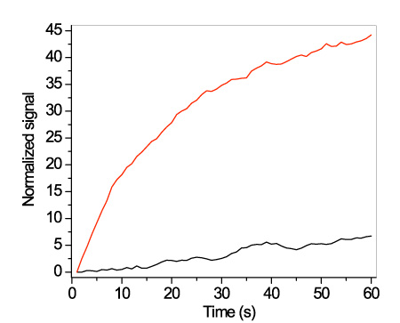
Figure 7. Real-time signal obtained during washing with a 0.125xHEN solution of the mismatching sequence (red line) or the full-matching sequence (black line) using a flow rate of 20 μl/min. In all cases, the signal is normalized with respect to its initial value.
c) Discrimination between full-matching and mismatching sequences – Kinetic versus end-point measurements
An important advantage of the NEMOSLAB sensor as compared to oligonucleotides microarrays is the ability to monitor in real time the signal changes upon hybridization and subsequent washings and perform kinetic instead of end-point measurements.
In Table 1 the discrimination between full-matching to mismatching sequences for the three mutations tested on chip are provided as ratios of fullmatch to mismatch signal calculated taking into account: a) the signals after 10 min of hybridization reaction, b) the hybridization rate during the first 30 s of reaction, c) the signal after washing for 1 min with 0.125xHEN solution and d) the dehybridization rate during the first 30 s of washing with 0.125xHEN.
Kinetic measurements especially during dehybridization upon washing with 0.125xHEN solution provided the most efficient discrimination between full matching and mismatching sequences even in cases where the initial hybridization failed to discriminate between the two reactions.
Table 1. Fullmatch to mismatch hybridization signal ratios obtained through end point or kinetic measurements with the NEMOSLAB sensor.
| M U T A T I O N | |||
| 3099delT | R1751X | 5382incC | |
| Final point of hybridization | 1.27±0.09 (n=10) | 0.27±0.04 (n=12) | 0.89±0.10 (n=11) |
| Hybridization rate calculated during the first 30 s | 1.21±0.11 (n=4) | 0.09±0.03 (n=4) | 1.85±0.13 (n=4) |
| Final point of dehybridization upon washing with 0.125xHEN | 8.4±0.5 (n=10) | 3.9±0.3 (n=12) | 12.4±1.5 (n=11) |
| Dehybridization rate calculated during the first 30 s of washing with 0.125xHEN | 38.4±3.1 (n=4) | 4.3±0.3 (n=4) | 14.4±1.2 (n=4) |
d) Sensor regeneration
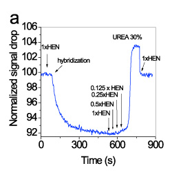
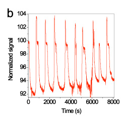
Repetitive regeneration of the hybridized target was accomplished using a 30% (w/v) urea solution. In figure 8a, the signal changes during a single hybridization-regeneration cycle were presented, whereas in figure 8b, the real-time signal during 9 regeneration cycles (10 hybridization and washing cycles) is provided. As it is shown, the immobilized probe could withstand at least five regenerations with 30% urea solution without loss in the signal.
|
|
Figure 8. Real-time signal obtained during a single regeneration cycle (a) and 9 consecutive regenerations (b). The signals were normalized with respect to their initial value.
NEMOSLAB instrument evaluation using fluorescently labelled PCR products
Chips spotted with probes corresponding to BRCA1 mutations R1203X & 3741insA were tested first with PCR products from a healthy individual and then, after sample 250, with combined PCR products from patients with the mutations R1203X & 3741insA.
The testing sequence was as follows:
1xHEN buffer: start to sample# 25
Combined PCR products from healthy individual DNA corresponding to mutations R1203X & 3741insA: sample# 25-100
Washing with 1xHEN: sample# 100-130
Washing with 0.5xHEN: sample# 130-160
Washing with 0.25xHEN: sample# 160-200
Washing with 0.125xHEN: sample# 200-235
Washing with 1xHEN: sample# 235-260
Combined PCR products from patients with the mutations R1203X & 3741insA: sample# 260-350
Washing with 1xHEN: sample# 350-400
Washing with 0.5xHEN: sample# 400-450
Washing with 0.25xHEN: sample# 450-500
Washing with 0.125xHEN: sample# 500-550
Washing with 1xHEN: sample# 550-end of run
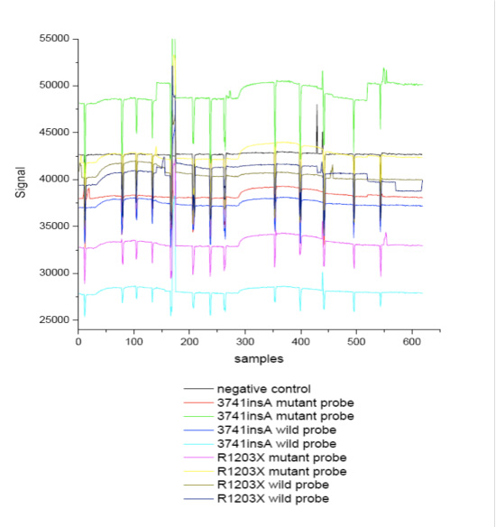
Figure 9. Real-time response from a chip spotted with probes as indicated in the legend during hybridization reactions with PCR products.
All waveguides coated with mutation specific probes provided response upon flow the PCR products corresponding either to wild-type or mutant-type individuals. The negative control waveguide did not show any response indicating lack of non-specific binding.
The mean specific hybridization responses as % signal increase were:
For the R1203X mutation:
wild/wild hybridization: 4.3±0.4
wild/mutant hybridization: 2.4±0.07
mutant/wild: 1.15±0.05
mutant/mutant: 4.85±0.35
For the 3741insA mutation:
wild/wild hybridization: 2.88±0.03
wild/mutant hybridization: 0.95±0.05
mutant/wild: 2.45±0.21
mutant/mutant: 3.56±0.28
The ratio of the signals obtained from the wild spotted waveguides tested with PCR product from healthy individual to that of mutant after washing was about 2-3 after washing with 0.5xHEN. On the other hand the ratio provided by waveguide spotted with the mutant type probe was about 1.5.
Single Binding Event Detection
a) Single binding event detection using particulate labels
Super-paramagnetic polystyrene particles with mean diameter of 1 micron and size distribution less than 3% covered with streptavidin have been tested as labels for single binding event detection by NCSRD. 8-micron wide fibers were coated with biotinylated BSA and after blocking a suspension containing 10-8 particles/ml is delivered to the surface. As it is shown in Figure 10, the binding of single particles is recorded as step-wise drop of the detector photocurrent. The fact that all the steps are not equal can be ascribed to different effect onto the waveguided modes upon binding of distinct particles onto the middle or the edges of the fiber.
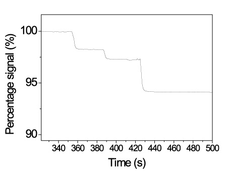
Figure 10. Real-time response from a chip spotted with probes as indicated in the legend during hybridization reactions with PCR products.
b) Single binding event detection using surface engineered vesicles loaded with light absorbing labels
Single binding event detection was also pursuit in the frame of NEMOSLAB project using surface-engineered lipid vesicles. These vesicles had an average diameter of 100 nm, were loaded with fluorescent labels and bore biotin moieties onto their surface so as their attachment through the biotin-streptavidin system to the solid-phase immobilized analytes to be possible.
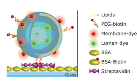
Figure 11. Schematic presentation of the surface-engineered lipid vesicles.
In Figure 12, the response from a waveguide coated with streptavidin upon flow of a solution of surface-engineered vesicles is presented. Arrow 1 indicates the introduction of vesicles solution into the flow channel and the arrow 2 the flow of washing buffer. The stepwise signal drop is indicative of single binding events taking place onto the waveguide surface.
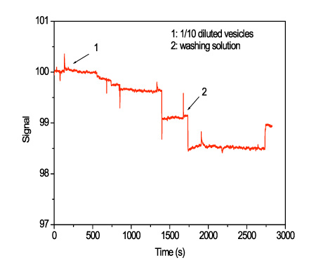
Figure 12. Real-time response from a waveguide coated with streptavidin during flow of preparation 1 vesicles at a 1/10 dilution in 80 mM NaCl, 10 mM phosphate buffer, pH 7.4. The flow rate was 100 μl/min.
