Direct Contacting Scheme and Packaging
The chip is placed in a cartridge and is inserted in an appropriate socket carrying a board to board connector (receptacle). The cartridge provides for the fluidic connection, while the board to board connector is part of the readout board with the control electronics, the LED bias and the detector signal amplifiers.
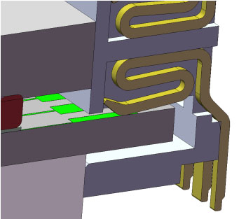
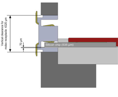
Detail emphasizing the way the receptacle is directly contacting the gold pads of the chips to achieve direct contacting and eliminate the need for expensive wire bonding.